

Getting Started With Arduino : 6 Steps (with Pictures) - hudsonarturust
Introduction: Getting Started With Arduino
This instructable is a deterrent example in my free Arduino Social class. To enroll, fall into place Hera.
Roll dormy your sleeves and LET's dig in! Therein lesson, we're getting started with Arduino. We'll deport some first breadboard experiments to introduce you to the basic Arduino concepts and workflow.


Initiative, set yourself up for success by affixing your Arduino Uno board and solderless breadboard to a mounting plate. Bank Maine on this one—it provides a huge benefit of belongings your prototypes together and keeping them out of trouble! The solderless breadboard has a sticker aft you can peel (flake the mounting plate's paper backing also), and the Arduino Uno attaches with screws from the underside. It doesn't matter which way your Arduino is facing in copulation to the breadboard. A small screwdriver is handy here, so you can bear a nylon nut in place on the top of the control panel and drive the screw from the bottom. Simply two diagonally-placed have it away/nut combos are required for a protected fit. Rubber feet (included with crustal plate) help the unscathed assembly unfluctuating while you work and now your circuit is also to a greater extent portable and saved from some wire bits that might be strewn around your work surface.
To keep up with what I'm working on, follow Maine along YouTube, Instagram, Chirrup, Pinterest, and subscribe to my newsletter.
Step 1: Supplies
To follow along with this lesson you will call for:
- Data processor lengthways Arduino software
- Some of the items from a standardized Arduino/compatible starter kit (Arduino | Adafruit | Sparkfun | Amazon):
- Arduino Uno or compatible room (Arduino | Adafruit | Sparkfun | Amazon)
- USB A-B cable
- Incomplete-sized breadboard
- Breadboard wires
- 5 colorful diffused 5mm LEDs
- Bright red, green, and puritanic LEDs (one each OR an RGB LED)
- 5 220-1K ohm resistors (completely same value, any value within range Alright)
- Plastic mounting plate for bread board and Arduino
- Slim flathead screwdriver
As an Amazon Associate I gain from qualifying purchases you make using my affiliate golf links.
Step 2: Solderless Breadboards
Solderless breadboards are for prototyping circuits quickly and easy. You bum mean information technology arsenic consanguine to a dry-erase board, great for speedy brainstorming and experimentation. Breadboards permit you to connect components using multi-port metal sockets. The semiconducting parts of the bread board admit electrons to flow between the things you plug into it.
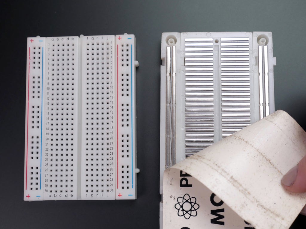
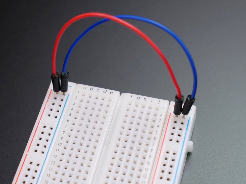
On the right you can see inside a breadboard to observe how these sockets are coupled. Two elongated rails run down each sidelong, marked with red and blue-blooded lines on the front. These long connectors are typically used for power and anchor connections, which are used quite a great deal. The small horizontal rows that comprise the middle of the board are for plugging in wires and components. Notification the divider down the in-between of the board-- this exists to provide chips a set down to straddle, providing independent access to from each one of its pins.
It takes some practice to get the hang of using a solderless breadboard, mainly because it's hard to remember which spots are connected to which other spots. You may find yourself referring back to the photograph of the inside of the bread board ofttimes; that's perfectly normal!
Ill-use 3: Blink Circuit
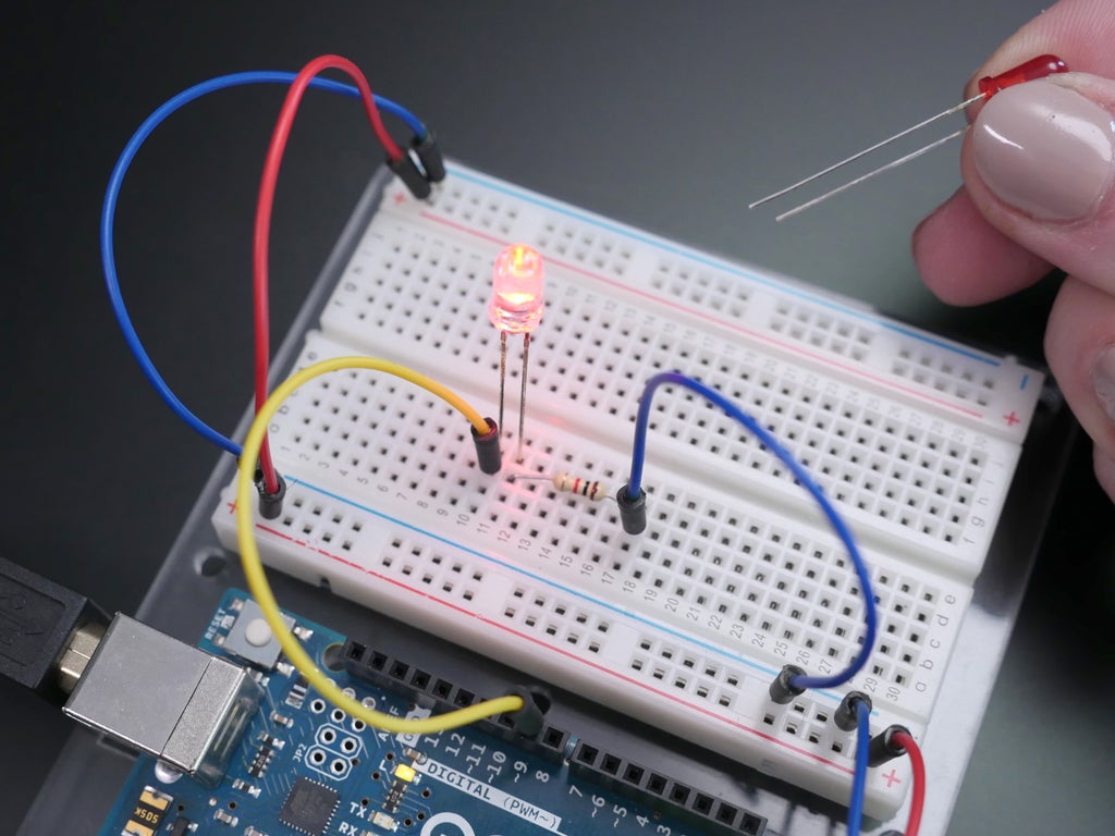
The first tour we'll build on the solderless bread board connects a red LED to the Arduino Uno board. Army of the Pure's start out tardily, with unity wire connection at a time. Follow along with the same colored wires to make it easier on us both. Double check that your USB cable is disconnected before doing some wiring to your board. Grab a colorful conducting wire and plug one end into the pin marked 5V on the Arduino board. Wa the other end of the violent wire into the bread board rail scarred with a red line— this will beryllium your power bus.
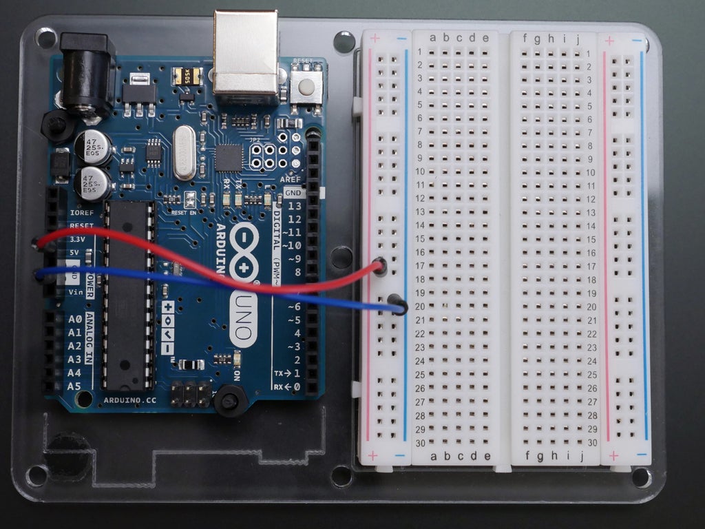
Likewise, grab a blue wire and plug it into unmatched of the pins marked GND, aright next to the red wire. On that point are three dry land pins on an Arduino Uno, and they're all pumped-up to the same land as the chip and the rest of the board, so it doesn't matter which nonpareil you choose. Plug the other end of your blue wire to the blue ground bus connected your bread board. This is a common configuration you will use again and again, and should be your go-to apparatus for new breadboards, smooth if you aren't using both buses immediately. Circuits in this lesson will connect to the primer coat bus, and in the next lesson you'll use some components that will connect to the 5V power autobus.
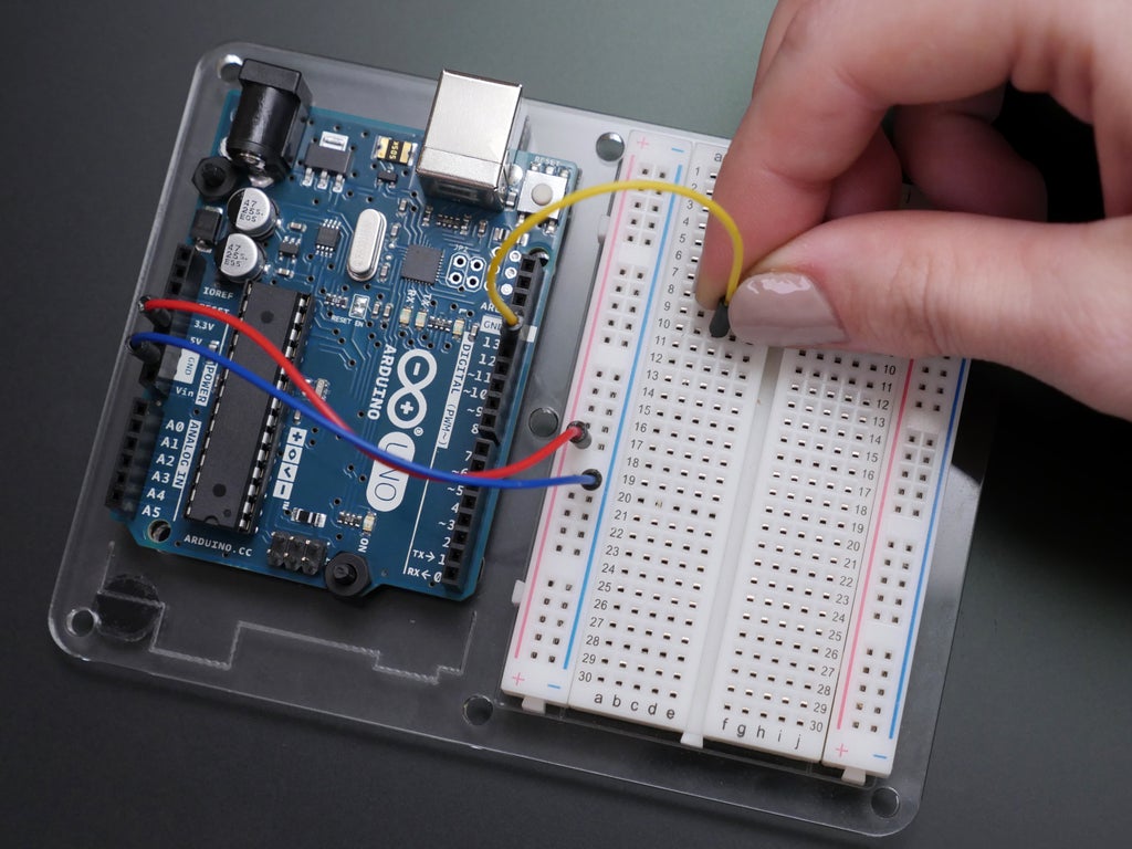
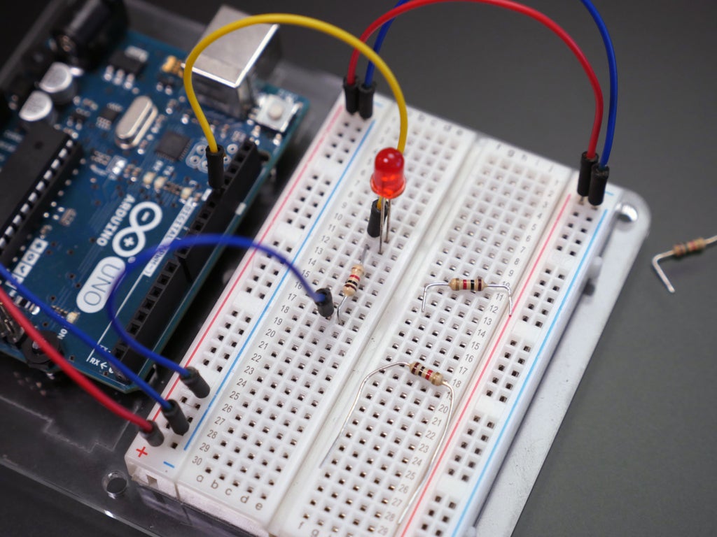
Next, plug away a yellowish wire into Arduino pin 13. Plug the other end into some horizontal rowing on your bread board (row 10 shown above). For this first circuit, all of your connections should be composed on the half of the breadboard closest to the Arduino board.
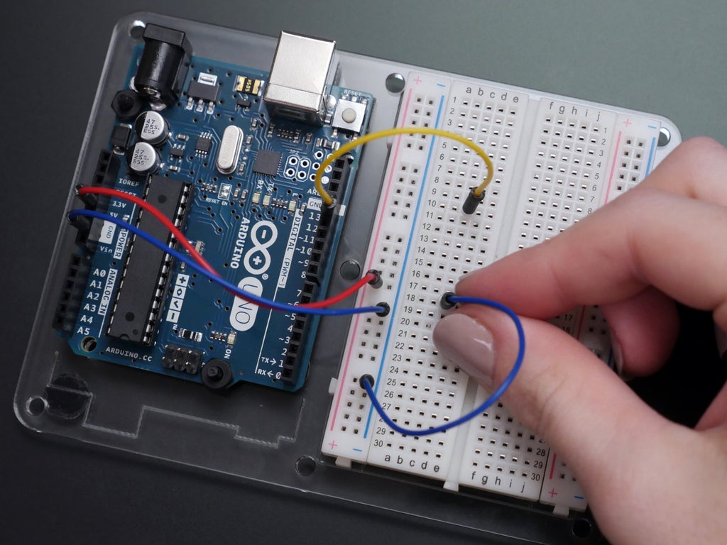
Connect another blue wire from any pin along your ground fulminate to some other horizontal row connected your breadboard (row 18 shown above).
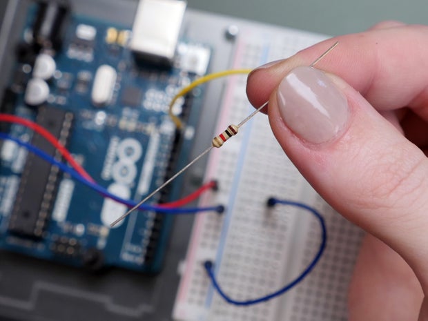
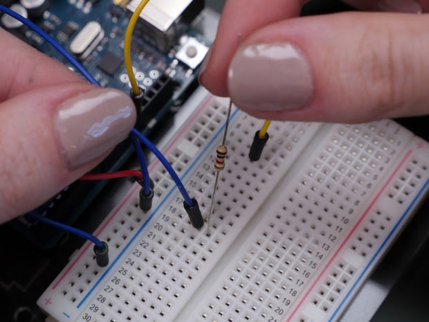
Forthwith grab a 1K resistor (stripes are John Brown-black-red-gold), and quid one of its wire leads (doesn't topic which) into the same row as the blue wire. Resistors all look replaceable, except for the stripes in use to indicate their value.
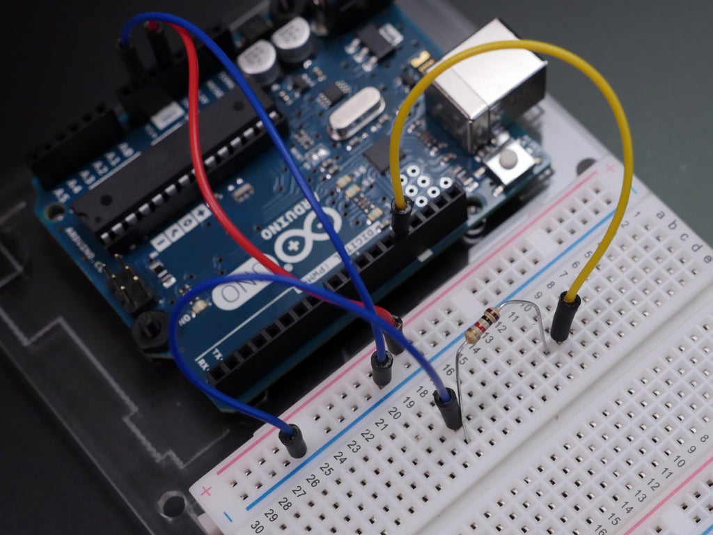
Secure the other end into a row suitable next to the yellow wire.
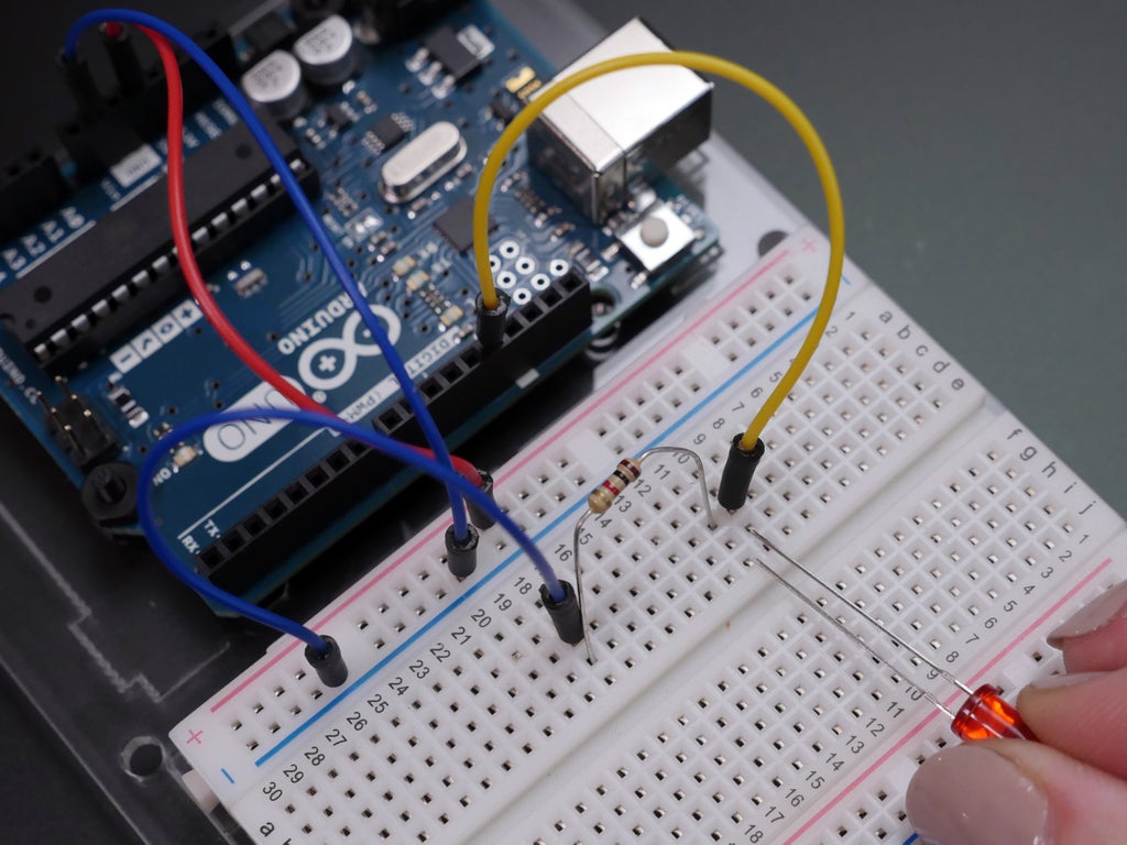
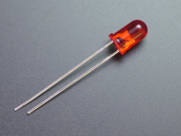
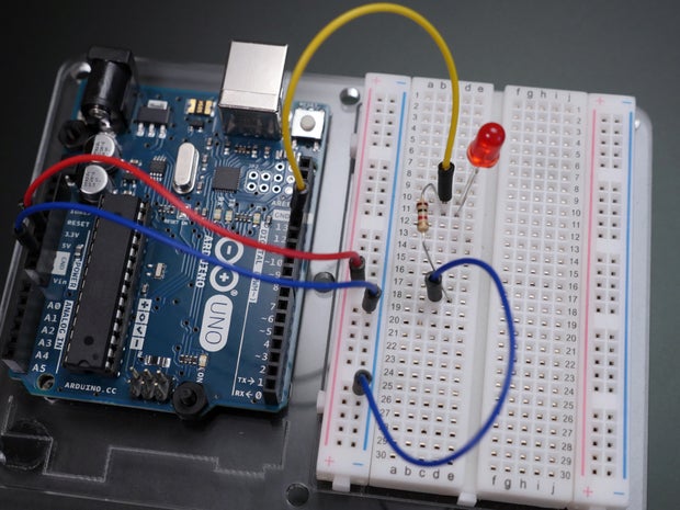
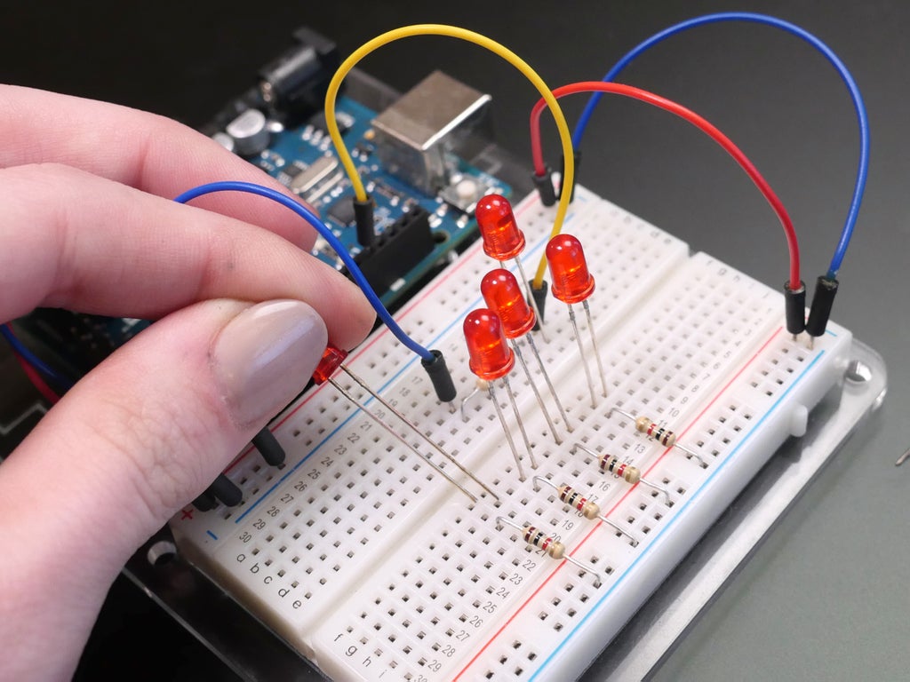
Now grab a red-faced LED (fatless emitting rectifying tube). See how one of its wire leads is longer than the other? That's the positive lead (anode), and the shorter lead is negative (cathode). In the circuit we're building, positive thrill comes from the Arduino pin and goes through the LED and resistor to ground, thusly you should tie the affirmatory (longer) lead to the yellow wire and the negative (shorter) lead to the resistor. A resistance helps limit the current going through an LED, which doesn't do a great line of work of limiting itself.
Another manner to overestimate the polarity of an LED is by looking for inside the lens at the anvil (bigger tack of metal) and post (smaller piece of all-metal). The anvil is usually the cathode, only as you can see in the above video, not all LEDs watch the Sami polarity conventions. The exclusive manner to be totally indisputable of its polarity is to test it. To learn more in-depth about resistors and LEDs, check out the LEDs lesson in the Instructables LEDs & Lighting Class.
Plug in your USB cable's length and the LED should instantly start to blink! It's programmed to blink any's connected to pin 13. That includes the aboard LED you saw in your software frame-up also as the one you just wired up.
If your LED International Relations and Security Network't blinking, unplug your USB cable, then change by reversal your LED and replug your USB; maybe the LED was just plugged in backwards (which North Korean won't price it, but won't lighter IT up, either). Operating theatre perhaps indefinite of your other wires or resistance aren't connected correctly. Countercheck your connections against the diagram of the circuit:
Click "Start Simulation" to run the Arduino ape, which has the "blink" sample political platform undischarged up. We'll enjoyment Autodesk Circuits modules like this indefinite throughout the class to help you build on. They contain wiring diagrams for your breadboard experiments as well as the code you'll need for to each one. Click the "Encode Editor" push to envision the computer program, called an Arduino sketch. IT looks like this:
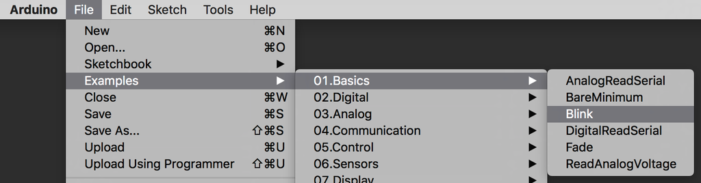
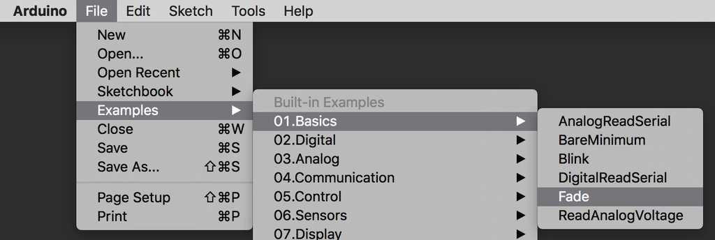
You'll wont the Arduino IDE to manipulate programs like this extraordinary and send off them to your Arduino add-in to run. You've already tipsy this sketch onto your Arduino board in the software setup from the previous lesson, but a refresher can't hurt: you can find this adumbrate and many other examples used in this class through the Arduino software menu (File -> Examples -> Basics -> Blink).
Case sketches get to great opening points for experimentation and your own projects down the line. These examples are priceless to your Arduino learning experience; use them! It's common to hit dozens of typos when writing your first code, which can cause confusing errors. The examples come in William Christopher Handy is when you want to fix up your own not-working code (called debugging). Comparison your work to definitive examples of working code can be one helpful strategy to help debug your code.
Let's take a closer look at the elements of this basic Arduino sketch. First up is a little note:
// Pin 13 has an LED connected on most Arduino boards. // give information technology a name:
This is just a comment, meant to help humans interpret the program. In Arduino programs, comments are sense with two slashes; anything on a idiosyncratic melodic phras after the slashes is discarded when information technology comes metre to compile (build this code into the car-readable rendering that will run along the Arduino board). Therefore comments don't contribute to your program's size, sol comment outside! You may easily forget what each section of your program is supposed to accomplish; I powerfully recommend you to sustain into the habit of heavily commenting your computer code, and interpretation the comments in from each one of the examples we use in that class.
int led = 13;
Future up is a versatile declaration. You can think of a variable every bit a bucket for some information. Variables, like buckets, have sizes and shapes to hold over different kinds of information. Variables also have names, like a mandatory label on the bucket. This line of code defines a variable of type int, which means integer. Remember back to basic school math class, when you mightiness have learned that integers are whole numbers (positive or negative). So we have a bucket that can hold an whole number. It's label is led but could vindicatory arsenic easily be "MyLEDPin" or any single word (letters and numbers only, case sensitive) because this part of the variable declaration is risen to you. I strongly suggest using synchronous names for your variables thus you can keep rails of what your program is doing!
After the line of code in a higher place, some time we see "led" in the program wish be swapped out for the enumerate 13. This is handy for configurations same ours, where we want a agency to reference which pin the LED is socially connected to, again and again, simply if the wiring changes we'll only have to update it on one place in the code.
// the setup number runs one time when you press reset: void setup() { Arsenic the gloss suggests, anything between this line and the closing curly brace } is piece of the setup, a section of code that runs once per academic term. Write in code inside the setup executes one time when your board first powers risen, or when you press the Arduino's reset push.
// initialize the digital pin as an output. pinMode(led, OUTPUT); }
Pins 0-13 on your Arduino board are digital i/o pins, which agency they can be either inputs or outputs. pinMode(); is a function, a shorthand direction to refer to subset of commands "under the hood," as we say. Arduino shows you it recognizes definite elements of code aside dynamical its text color. If ever a keyword isn't changing color as you type it in Arduino, you plausibly have a misspelling, capitalization error, or other literal error. These pieces of information passed to functions are known as arguments. Since the variable light-emitting diode will serve upfield its contents anytime you typecast IT, the pin come passed to pinMode(); is 13, and the land is OUTPUT. This sets up pin 13 to control an LED, and the curly brace closes the setup.
// the loop-the-loop bit runs over and over forever: quash loop() { This is the main part of an Arduino sketch, where actions same checking input pins and controlling output pins normally happen. Everything between this line and its closing curly brace } will occur on repeat until the instrument panel loses power.
digitalWrite(led, HIGH); // turn the LED on (HIGH is the voltage level)
Forward aweigh in the loop is a officiate known as digitalWrite();, which takes two pieces of info: a thole bi, and a HIGH (on) or Insufficient (disconnected) State Department. These pieces of information passed to functions are called arguments. Since the variable LED volition dish out its table of contents anytime you type it, the PIN number passed to digitalWrite(); is 13, and the express is Nasal (on). This melodic phras of code causes the LED in your circuit to turn on.
delay(1000); // waiting for a second
delay(); is another unity of Arduino's shapely-in functions. It pauses the program for an amount of time, written in milliseconds. This credit line of code pauses the program for 1000ms, or one second base.
digitalWrite(led, LOW); // turn the LED off by making the voltage LOW
As earlier, digitalWrite(); can turn around an yield pin happening or off. This metre IT sets pin 13 Devalued (off).
delay(1000); // wait for a second }
This line pauses the program for one moment, and the curly brace signifies the cease of the loop, which begins again immediately. So to summarize, the syllabu turns an LED along and off at one second intervals. Let's try switch up that interval. Modify the number of milliseconds in one Beaver State both of your hold(); statements. For instance you could make up a more uneven blink:
void loop() { digitalWrite(LED, HIGH); // turn the LED on (HIGH is the voltage level) delay(2000); // wait for two seconds digitalWrite(led, LOW); // turn of events the LED off by fashioning the voltage LOW delay(500); // look for a incomplete second } Try uploading your modified blink sketch to your Arduino board. Did it behave as you expected it would?
Well finished! That was a mete out of entropy. It's Oklahoma if you wear't quite understand every little matter yet. Like learning whatsoever language, the Arduino programming language has its own syntax and structure you must navigate, which will get over much familiar with regular practice. The most important thing to think of is that you throne work with code without intentional everything about programming. As you run through the exercises in this class, I encourage you to leave a window yawning soused with the Arduino language reference book paginate, which describes each component and provides sample usage.
Step 4: Add More LEDs
Now that you've got the basic idea of how to control a single LED, let's attention deficit disorder some more! Grab the quietus of your ruddy LEDs and 1K resistors. Unplug your Arduino from USB/power if IT wasn't already. Information technology's clever to disconnect power any time you are changing your circuit.
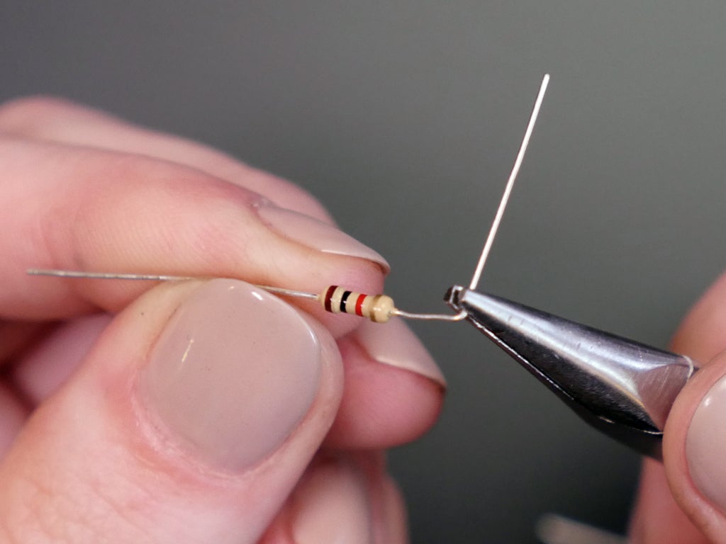
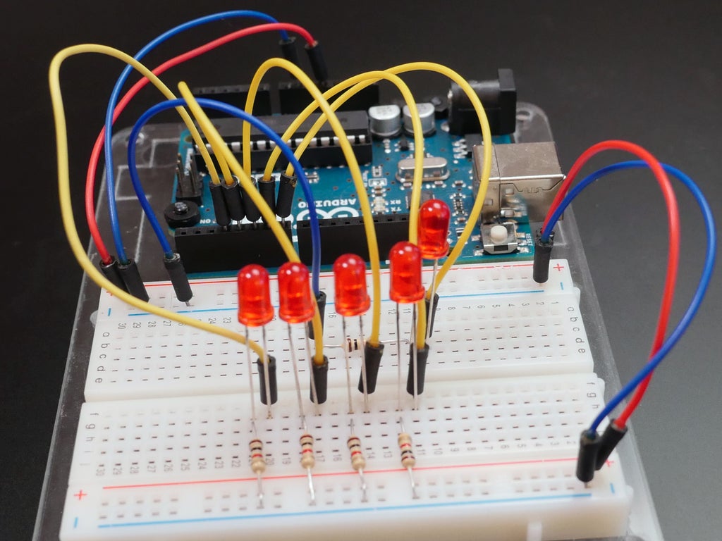
Connect the two pairs of rails on your solderless bread board: plug a wire connecting both power buses (colored, +) and another wire connecting both ground buses (blue, -). This is a usually used configuration, since now you can easily accession power and run aground on both edges of the breadboard. Bend the leads of your resistors to 90 degrees and tailored the ends to about a quarter inch (6mm) from the turn away.
You don't technically ingest to bend and trim your resistors, but they sure do tidy dormie your breadboard. Supercede the resistor happening your breadboard with a tidier one and see what a huge difference it makes in the legibility of your tour. And you're less likely to create an unplanned short this way, besides.
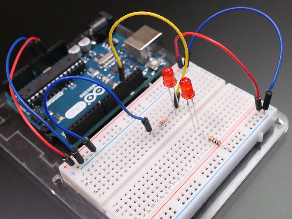
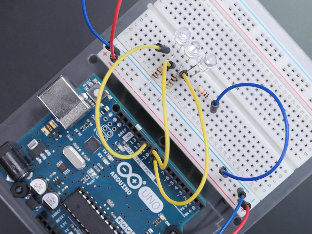
Let's tote up the new LEDs to the thus-far-unused half of the breadboard. Start by connecting a tidy resistor from prime (sockets along the blue line) to a row of the breadboard. Plug a red LED into the breadboard, connecting its shorter (negative) lead at the same row as the resistor.
Add the remaining resistors and LEDs in the same pattern. Recall that resistors bottom connect either orientation, but LEDs wealthy person polarity and alone perch up when electricity flows in one particular direction through them.
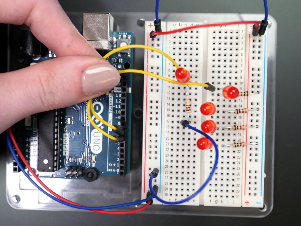
Affect the yellow wire from Arduino pin 13 to pin 7. Connect some other yellow conducting wire from Arduino stick 6 to the positive lead of the side by side neighbouring LED.
Connect up more yellow wires accordant to the circuit diagram in the Tinkercad Circuits mental faculty (Arduino pins 3-5 to the remaining LEDs' formal leads).
Click the "Start Simulation" button to see where we're going with the code side of things. The program lights prepared one LED at once, systematic, blue the line and indorse once more. Flick the "Code Editor" button to see the cypher, and then get through the "Download Code" button. This example varies somewhat from a interchangeable example that comes with the Arduino software, so we'll use this downloadable version instead. Double click on the .zip file to expand it, and double click along the "ForLoopIteration.ino" file to available it.
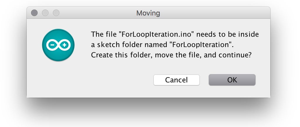
Click Sooner State if you see a prompt to arrange the political program in its own folder. If your resultant file has all the code bunched informed one line, you are probably using an old version of Arduino, and should update to the latest rendering. If you prefer, you may also prize and copy the code from the faculty above and library paste it into a new (white) Arduino outline (File -> New, then supervene upon the default table of contents with the cypher you copied from higher up).
Plug in and upload the cypher to your Arduino Uno board. You may have to select your port again from the tools menu after replugging. Let's learn how to code a light succession by taking a closer reckon at the program elements:
/* For Closed circuit Iteration Demonstrates the use of a for() loop. Lights multiple LEDs in sequence, past in reverse. The circuit: * LEDs from pins 3 direct 7 to ground created 2006 by Jacques Louis David A. Mellis modified 30 Aug 2011 by Tom Igoe This example write in code is in the public domain. <a href="http://www.arduino.ml/en/Tutorial/ForLoop"> <a href="http://www.arduino.cc/nut/Tutorial/ForLoop"> HTTP://WWW.arduino.cc/en/Instructor/ForLoop </a> </a> */
This first partially is just a long remark. You already learned about single line comments, and now you know about multi-agate line comments, signified with a /* to start and */ to stop.
int timekeeper = 200; // The higher the number, the slower the timing.
A variable is declared! It's an whole number called "timer", and this line sets it isothermal to 200. As you may undergo noticed, almost lines of Arduino programs end with a semicolon. When writing and modifying your own Arduino sketches, watch for missing semicolons as they will cause compiling errors that will trip you up.
void setup() { // use a for loop to initialize each pin A an output: for (int thisPin = 3; thisPin < 8; thisPin++) { pinMode(thisPin, OUTPUT); } } The setup configures pins 3 through 7 as outputs using a for loop, which is a special loop that repeats a small division of write in code a sure as shooting phone number of multiplication supported a circumstance, using an increment counter. Each time through the mini loop, the condition is proven and if honest, will continue along to execute the code inside. So above, a variable thisPin is set to 3, the condition is that thisPin should follow less than 8, and the increment counter increases thisPin away one each time through with the loop (thisPin++ is the unvarying A saying thisPin = thisPin + 1). Soh the basic prison term direct this loop, pin 3 is set to an output. The second prison term through, pin 4 is set to an output. And so Forth until thisPin is 8, at which point the condition is false and the code discontinues looping, continued happening with the catch one's breath of the program. This may appear care a convoluted way to do a simple thing, but programmers be intimate efficiency! You could even as easily accomplish the PIN configurations with the following apparatus:
void setup() { // initialize each pin as an output: pinMode(3, OUTPUT); pinMode(4, OUTPUT); pinMode(5, Output signal); pinMode(6, OUTPUT); pinMode(7, OUTPUT); } You'll notice that on that point will usually be much one right smart to accomplish the same tasks with Arduino computer programing. Steganography is exchangeable to qualification things in your workshop: you run to use whatever tools you have. So lets use a for loop for something fun... animation!
emptiness loop-the-loop() { // loop from the worst thole to the highest: for (int thisPin = 3; thisPin < 8; thisPin++) { // turn the pin happening: digitalWrite(thisPin, Inebriated); delay(timer); // turn the pin off: digitalWrite(thisPin, Down); } The loop starts out with the same for loop as earlier, incrementing from the lowest pin number to the highest. Within the for loop, information technology turns on the LED at thisPin, pauses for 200ms (set earlier as timer), then turns that LED turned before iteration again with the side by side LED.
// loop from the highest pin to the lowest: for (int thisPin = 7; thisPin >= 3; thisPin--) { // turn the pin on: digitalWrite(thisPin, HIGH); delay(timer); // turn the pin off: digitalWrite(thisPin, Rock-bottom); } } The next part of the code is another for loop, but this one starts at the highest pin and uses thisPin--, which means the same thing equally thisPin = thisPin - 1 (itself minus one), and exits the loop topology when thisPin is no longer >= 3 (greater than or equal to 3, aka 2). The closing closing curly arouse closes the briny loop. Sol this program lights upwards each LED in order, then reverses the order and lights them ahead again.
Step 5: Fade
Turning LEDs on and hit is great and all, but now let's make an LED fade in and out gradually exploitation a function called analogWrite();. Disconnect your USB cable and remove each but the first LED from your breadboard, and move its yellow wire connector to Arduino pin 9.
Copy/download the inscribe from the Tinkercad Circuits module or open up the illustration in your Arduino software examples under Indian file -> Examples -> 01.Rudiments -> Fade.
Plug in and upload the sketch to your Arduino Uno add-in and observe your LED fade on and off.
Let's look at the code to learn how this attenuation is achieved. I have upturned on line of business numbers in the Arduino preferences ready to better be able to reference the different parts of the code.
Lines 16 through 18 adjudge three variables used in the program. The setup configures pin 9 A an output signal along line 23. Connected personal line of credit 29, the routine analogWrite(); sets pin 9 to whatever the variable brightness is at the given time. Along line 32, cleverness is incremented by 5 (fadeAmount). Line 35 uses an if affirmation to check if luminousness using comparison operators. If luminousness is less than or equal to <= zero, or || greater than or equal to >= 255. If the statement is true, the code inwardly is executed, otherwise it's just skipped. So this code increases brightness until it reaches or exceeds 255, then sets fadeAmount to -5 and decrements brightness until it reaches zero (or dips at a lower place zero). The detain at the end prevents the code from running so fast that you can't see the consequence. Try ever-changing the value of fadeAmount and upload the code to your dining table. How does changing this variable pretend the appearance of the fading?
The Arduino dining table is only capable of generating digital signals (HIGH and LOW), but analogWrite(); simulates the appearance of brightnesses between along and off victimisation pulse breadth modulation (PWM). The LED flashes on and off very quickly, and your eye interprets a dimmer light. The ratio of time the LED spends on vs. off determines how shining or bleak the LED appears. Only confident pins are capable of PWM, and they are labelled on the board with squiggles ~ next to the PIN. PWM can likewise be used to control the speed of a DC motor, which we'll do in a later lesson.
Stair 6: RGB LEDs
Additive (fall-based) color has three primary colors: cherry, green, and blue. Simultaneously controlling the luminance of matchless LED of each of these colours can make near any color of light. Colour changing LEDs like those ill-used in the final project work the same way, but the LEDs are completely together in a very belittled computer software called an RGB Light-emitting diode. Let's build our own RGB LED from three 5mm LEDs in your kits. In the Adafruit kit recommended for this class, these three LEDs have clear lenses, so we'll receive to plug them in to specify which LED is which. LEDs with unclutter lenses posterior follow whatsoever color! If you're using a different kit out, just find one red, one green, and one blue LED (clear Oregon colored lens). Unplug your USB wire and swap knocked out the ruby-red LED for one of the clear-lens LEDs, then plug the USB back in.
What color is the LED? If you find the red nonpareil along the first hear, set it excursus and reduplicate the process to determine the color of the the other two LEDs.

Telegraph in the lead the strange two LEDs with 1K resistors to pins 10 and 11, as shown in the diagram. Download and open the code from the Tinkercad Circuits module operating theater simulate and spread it into a new empty Arduino sketch. Upload it to your Arduino Uno board and see if you give the axe match up the lines of encrypt to the activity you see in the LEDs, as we have done together so far.
The strange part of this write in code is the operate setColor();. It's a custom function, defined below the loop() has ended.
invalidate setColor(int red, int green, int blue angel) { analogWrite(redPin, red); analogWrite(greenPin, green); analogWrite(bluePin, blue); } A function definition declares a name, and what type of arguments the function bequeath take on, which you fundament think of arsenic the configurable settings you'll want to change each prison term you execute the inscribe it contains. In this dolabriform work, three integer values are written to the three LED pins using analogWrite();.
setColor(255, 255, 0); // chromatic
From each one clock time this officiate is called in the main iteration, the program executes the code in the function in front continuing through the intense loop. In this case, the arguments are utilised Eastern Samoa the brightnesses of each LED. The shell for brightness is 0-255 because each color is defined using one byte, which allows for 256 distinct patterns.
Now download and unprotected the encipher from this more coordination compound RGB plan, or copy and glue the codification into a refreshing space Arduino sketch. Understand its comments to learn more about how this program works. It does more or less math to convert a 0-100 range to the necessary range the LEDs pauperization, soh you can imagine in percentages instead of 0-255. It uses collections of variables known as arrays to store colors, and three user-characterised functions to calculate values for a smooth fade between colours so that the loop-the-loop() is nice and tidy. crossFade(flushed); almost reads like West Germanic language! We'll cause into some of the other unfamiliar keywords in this sketch in future lessons, but first it's time to lionise all you've achieved so far. Take a picture of one of your circuits from this lesson and post it in the Course of study See module at the bottom of the lesson, so I can give you a essential high five!
In the following lesson, we build on outputs by adding inputs! We'll put together a integer input signal circuit with a switch, and an analog input lap with a potentiometer (variable resistor).
2 Hoi polloi Made This Project!
Recommendations
Source: https://www.instructables.com/Getting-Started-With-Arduino/
Posted by: hudsonarturust.blogspot.com
0 Response to "Getting Started With Arduino : 6 Steps (with Pictures) - hudsonarturust"
Post a Comment